
User talk:Msiddalingaiah
Welcome!
Hello, Msiddalingaiah, and welcome to Wikipedia! Thank you for your contributions. I hope you like the place and decide to stay. Here are a few good links for newcomers:
- The five pillars of Wikipedia
- How to edit a page
- Help pages
- Tutorial
- How to write a great article
- Manual of Style
I hope you enjoy editing here and being a Wikipedian! Please sign your name on talk pages using four tildes (~~~~); this will automatically produce your name and the date. If you need help, check out Wikipedia:Where to ask a question, ask me on my talk page, or place {{helpme}} on your talk page and someone will show up shortly to answer your questions. Again, welcome!
Images[edit]
Thanks for uploading Image:NPN Colpitts oscillator collector coil.png. I notice it currently doesn't have an image copyright tag. Could you add one to let us know its copyright status? (You can use gfdl if you release it under the GFDL, or fairuse if you claim fair use, etc.) If you don't know what any of this means, just let me know where you got the images (on my talk page)and I'll tag them for you. Thanks so much,
BrokenSegue 03:37, 16 Feb 2005 (UTC)
Math markup[edit]
Just a heads up.
There's no need for images of most mathematical formulae because the wiki can do math markup see m:Help:Formula User:Zeimusu
Electronics contribution[edit]
Hi,
The content so far is quite impressive. I have a lot of experience in both analog and digital electronics. I'd like to contribute, but I'm not sure where I should focus my efforts.
There's a fair amount to be done wrt oscillators and filters.
Any suggestions? - Madhu
- Just start editing! Here are some things I was going to work on but either no motivation or I just don't know enough about them:
- RC circuit
- RLC circuit
- Electronic filter - This needs a list of butterworth, chebyshev, etc. and diagrams?
- Electronic oscillator
- - Omegatron 22:56, Feb 16, 2005 (UTC)
- Excellent work with the oscillator articles. Did you already know all this or are you adding it as you learn? I'd like to know how a crystal oscillator is (induced? forced?) to pick a specific vibration frequency, considering the crystal can vibrate in many different modes and harmonics. - Omegatron 23:17, Mar 28, 2005 (UTC)
- Thanks! I learned much of the oscillator theory many, many years ago when I worked as a summer intern at NASA/Goddard. My mentor was a highly insightful, very old school engineer by the name of Leonard Kleinberg. He holds many patents on several novel oscillator designs. One of his best designs can be found here It took me years to really appreciate all of the math he regularly threw at me, but some of it finally sunk in. I've been refining it over the years, Wikipedia gave me a good a place to publish and preserve it. I had to re-derive much of it as I didn't keep any notes. The derivations you see are all my work, I have not seen it published anywhere else.
- Crystal oscillators can be tricky. I've spent many years working on overtone oscillators that didn't work! The answer is quite simple. Crystal oscillators are no different than any other oscillator. Oscillation will ocurr at a frequency where phase is zero and gain is greater than one (Barkhausen criteria). Stated differently, oscillation will ocurr at a frequency where total resistance is zero. In general, the losses increase with frequency, so the fundamental is the most likely mode. If you want to pick a specific overtone, add an LC tank that adds phase at all other frequencies or change the circuit to produce negative resistance only at a particular overtone. I've had success both ways, but one of the easiest ways is to build a standard LC oscillator near the overtone you want and put the crystal in series with the feedback loop. The crystal exhibits wild swings in reactance (and phase) near overtones, so the oscillator frequency shifts to make the crystal happy. Of course, you have to be close to an overtone or you will get the LC frequency, which isn't interesting. Madhu 02:39, 30 Mar 2005 (UTC)
- Neat. That makes 90% sense, and the rest I will stare at some circuit diagrams to get. Complete understanding is on the tip of my brain...
- As for keeping notes, teaching, and learning, I've found wikipedia to be a sort of "communal notebook". I try to write things here as I learn them, and, when I invariably forget something, it is easy to find where I wrote it down. At the same time, other people can read and learn from it (and fix things I got wrong!) Also, one of the best ways to learn something is to put it into words for someone else to read. - Omegatron 04:28, Mar 30, 2005 (UTC)
Modular electronics diagrams[edit]
What do you think of this?
Wikipedia:Village_pump_(proposals)#Modular_electronics_diagrams - Omegatron 00:57, Mar 6, 2005 (UTC)
Helical antenna[edit]
Hello,
I have a question for you about one of your edits to the helical antenna article. The gain formula you entered seems to give rather high values, e.g. with the following setup:
f = 3GHz → λ = 0.1m
N = 10
C = 0.1m
S = 0.1m
you get:

whereas most helical antennae I've seen on the market have gains in the 13-16 dB range. Is there something wrong with the formula, or just my use of it?
Whitepaw 13:14, 2005 May 9 (UTC)
- I think the equation is right, at least it's the same as the one found at this website: http://www.geocities.com/CapeCanaveral/Hangar/8092/ch3.html
- I think you have a bad value for S, which is the spacing between turns. The numbers above results in a straight wire, I think?? Also the directive gain is not in dB, I should probably have mentioned that in the article... Madhu 22:14, 10 May 2005 (UTC)
Ratings for commercial generators[edit]
Hi! It sounds like you might have worked the power industry, so I had a quick question: I toured a local coal fired plant here in the DC area. They had three generators, two were operational, one was offline at the time. Each was a 200 MW unit, surprisingly small, IMHO. Anyway, I think the output voltage at the generator terminals was something like 14 kV, but I can't remember, I could be wrong. If it is 14 kV, then the current would be around 14200 AMPS! That seems like a lot of current. If it is correct, the wire in the windings would have to be around 3 inches or so. Do I have my numbers wrong? The voltage couldn't be much more, even if it was double, that's still some very thick wire!! What do the windings look like in that size generator?? Can't be many turns... Madhu 19:33, 2 September 2005 (UTC)
- Sounds about right - generators of that size are usually wound for a medium voltage (around 15 kV up to about 30 kV), and so the currents are very high. The machines are large so there's lots of room for very heavy copper windings; often these machines are cooled by water coils in the stator or by circulating hydrogen gas in the generator enclosure. The windings are made of something called "Roebel bars", which is a rectangular section of copper with individual strands insulated from each other (for eddy currents), and the whole covered with insulation rated for the terminal voltage of the machine. Large generators don't need many turns on each pole because the poles are large; there's a lot of flux linked and so each turn produces more voltage - there could be only 3-4 bars in each slot for a 15-kV class machine. The company ABB developed a concept called "Powerformer" in which high-voltage cable was used to make the windings; this allowed them to build a generator that directly produces transmission voltage (115,000 V or higher) but so far they've only built a few units. Utiltities are very cautious and the technology is still very new. 200 MW is not the largest rating in the world but is still pretty big - in Manitoba where I live, the utility doesn't have any single generator as large as 200 MW in a total installed capacity of nearly 5000 MW. Utilities often would prefer to have 3 -200 MW units instead of one 600 for reliability reasons. --Wtshymanski 15:39, 4 September 2005 (UTC)
New category[edit]
Based on your user page, this may be of interest to you: [[Category:Wikipedians who are pilots]]. Best regards, CHAIRBOY (☎) 17:04, 18 December 2005 (UTC)
Helicopter rotor[edit]
Wow! Thanks for the history and generally helping to build this page. A pointer - when you include a link with a space in the name, you don't have to include an underscore. Just leave a space; Wiki will do the right thing! Benet Allen 20:06, 25 December 2005 (UTC)
- Thanks! Much of the history about Cierva is from memory, I read it many years ago, so it could use some expert review. Yeah, I often copy links from the URL textfield in my browser, so the underscore shows up :-( We really need a nice 3D drawing of a rotor head, swash plate, hinges, links etc. I'm not much of an artist, though... Madhu 00:56, 26 December 2005 (UTC)
Quotes[edit]
Hi Can I steal your quotes ? - CPES 04:03, 28 April 2006 (UTC)
- Well, they really aren't my quotes, so I can't claim any ownership. I won't complain if you include a link to my website :-) Madhu 00:59, 8 May 2006 (UTC)
- I saw this quote "An engineer is someone who will spend 3 hours figuring out how to solve a 2 hour problem in one hour" here and so I thought you would appreciate this one I heard a while back:
- A half a glass of water sits on a table. An optimist sees the glass as half full, a pessimist sees the glass as half empty, an engineer sees that the glass is twice as big as it needs to be. Alfred Centauri 00:43, 15 March 2007 (UTC)
Question[edit]
Hi
Could you please tell me how to figure out the maximum current that a solenoid would draw? Also the formula in your page,
F = μ N^2 I^2 A/ 2g^2
So does the surface area of the ferromagnetic material being attracted have no effect?
thanks,
--Thecoolsundar (talk) 14:19, 22 August 2010 (UTC)
- It is dependent on area, A is the area in the above equation. The assumption int this case is there are no fringing field lines. This is a reasonable assumption if the permeability of the materials is high and the gap is small. The current through a solenoid is limited by it's impedance. At DC, the impedance is the resistance of the coil. With AC, it's the sum of the resistance plus the inductive reactance of the solenoid.
Hi,
So this is what I did,
I took a cylinder of steel of Dia 44.7mm and wrapped insulated copper wire around it 148 times. The resistance of the winding was 9 ohms. I also connected a 100 ohms resistor in series with it and applied 24V DC to it.
So now;
μ = 4Π * 10^-7 N/A^2
N = 148
I = 24/109 = 0.22A
A = 1569.5 mm^2
g = 0.3 mm
So F = 12.56*10^-7 (21904)(0.0484)(1569.5)/2*0.09 = 11.61 N
Right? So it should lift a mass of 11.61/9.8 = 1.18 Kg Right?
But it doesn't. Infact it doesn't even lift 1/4 that.
Why? What am I not understanding?
Thanks
59.92.156.22 (talk) 12:58, 26 August 2010 (UTC)
Sorry the preceding question was me but I forgot to sign in
also the length of the steel cylinder is 25.5mm
Thanks --Thecoolsundar (talk) 13:01, 26 August 2010 (UTC)
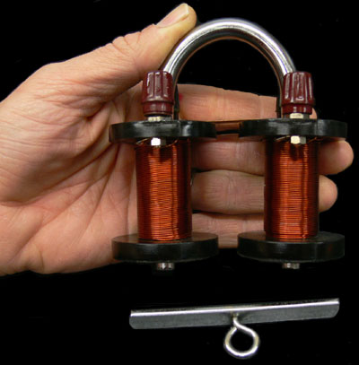
- A straight cylinder with only one magnetic pole in contact with the load won't be very effective. The air gap includes the distance from each pole with the load in between, which is much larger than your estimate above. A complete magnetic circuit is best. You need to have both pole faces in contact with the load to achieve good lifting capability. You can use a U-bolt similar to a horse shoe magnet. You should file or grind the contact surfaces to a flat finish to get best results. Another common geometry uses two concentric cylinders closed at one end with windings around the inner cylinder. Industrial electromagnets commonly use concentric cylinders. Also, your units are not consistent. If you want to use MKS units, use meters for length, not mm. Madhu (talk) 22:21, 2 September 2010 (UTC)
File:Colpitts ideal model.png listed for deletion[edit]
A file that you uploaded or altered, File:Colpitts ideal model.png, has been listed at Wikipedia:Files for deletion. Please see the discussion to see why it has been listed (you may have to search for the title of the image to find its entry). Feel free to add your opinion on the matter below the nomination. Thank you. Sfan00 IMG (talk) 21:01, 2 August 2013 (UTC)
Hi,
You appear to be eligible to vote in the current Arbitration Committee election. The Arbitration Committee is the panel of editors responsible for conducting the Wikipedia arbitration process. It has the authority to enact binding solutions for disputes between editors, primarily related to serious behavioural issues that the community has been unable to resolve. This includes the ability to impose site bans, topic bans, editing restrictions, and other measures needed to maintain our editing environment. The arbitration policy describes the Committee's roles and responsibilities in greater detail. If you wish to participate, you are welcome to review the candidates' statements and submit your choices on the voting page. For the Election committee, MediaWiki message delivery (talk) 12:58, 23 November 2015 (UTC)
File:Colpitts ideal model.png listed for discussion[edit]

A file that you uploaded or altered, File:Colpitts ideal model.png, has been listed at Wikipedia:Files for discussion. Please see the discussion to see why it has been listed (you may have to search for the title of the image to find its entry). Feel free to add your opinion on the matter below the nomination.
ATTENTION: This is an automated, bot-generated message. This bot DID NOT nominate any file(s) for deletion; please refer to the page history of each individual file for details. Thanks, FastilyBot (talk) 23:50, 17 September 2016 (UTC)
ArbCom Elections 2016: Voting now open![edit]
Hello, Msiddalingaiah. Voting in the 2016 Arbitration Committee elections is open from Monday, 00:00, 21 November through Sunday, 23:59, 4 December to all unblocked users who have registered an account before Wednesday, 00:00, 28 October 2016 and have made at least 150 mainspace edits before Sunday, 00:00, 1 November 2016.
The Arbitration Committee is the panel of editors responsible for conducting the Wikipedia arbitration process. It has the authority to impose binding solutions to disputes between editors, primarily for serious conduct disputes the community has been unable to resolve. This includes the authority to impose site bans, topic bans, editing restrictions, and other measures needed to maintain our editing environment. The arbitration policy describes the Committee's roles and responsibilities in greater detail.
If you wish to participate in the 2016 election, please review the candidates' statements and submit your choices on the voting page. Mdann52 (talk) 22:08, 21 November 2016 (UTC)
ArbCom 2017 election voter message[edit]
Hello, Msiddalingaiah. Voting in the 2017 Arbitration Committee elections is now open until 23.59 on Sunday, 10 December. All users who registered an account before Saturday, 28 October 2017, made at least 150 mainspace edits before Wednesday, 1 November 2017 and are not currently blocked are eligible to vote. Users with alternate accounts may only vote once.
The Arbitration Committee is the panel of editors responsible for conducting the Wikipedia arbitration process. It has the authority to impose binding solutions to disputes between editors, primarily for serious conduct disputes the community has been unable to resolve. This includes the authority to impose site bans, topic bans, editing restrictions, and other measures needed to maintain our editing environment. The arbitration policy describes the Committee's roles and responsibilities in greater detail.
If you wish to participate in the 2017 election, please review the candidates and submit your choices on the voting page. MediaWiki message delivery (talk) 18:42, 3 December 2017 (UTC)